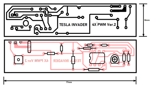
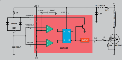
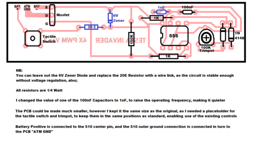
I recently rebuilt a Tesla Invader 4X for a mate, (the original pcb was irreparable), and thought I'd share the circuit diagram and PCB layout should anyone else wish to resurrect / convert a failed mod.
This modification replaces the PCB in it's entirety, and requires minimal wiring changes. It will however no longer have in situ charging, (does anyone use that anyway?), and ... I did away with the led's, (who looks at them whilst vaping anyway?).
The board layout as presented below will use all the existing pcb mounting and share the existing case firing button and pcm adjustment knob.
All the components are available from Mantech, (who will also make up the PCB below if required).
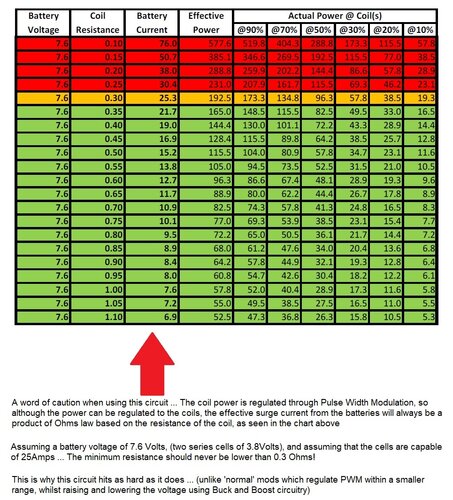
The Mosfet I used is rated at 59Amps Continuous, and the PCM will adjust from 1 through 99% of the available voltage of two 18650's in series, (without any protection! ... so you may wish to add a PTC rated at around 30Amps in series with each battery).


Attachments
Last edited:


