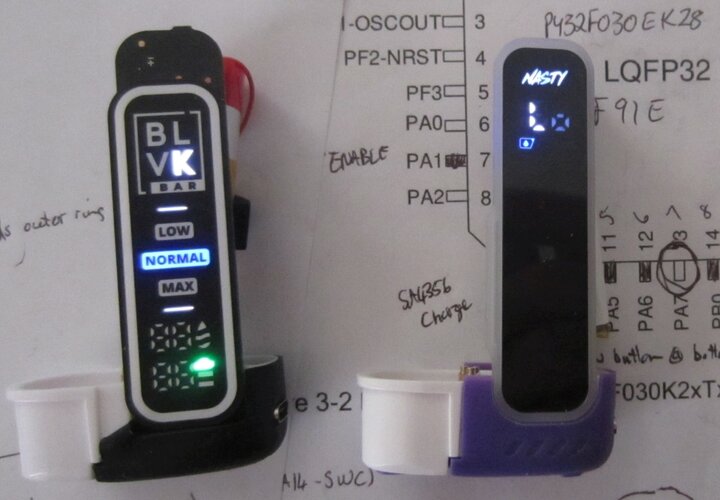
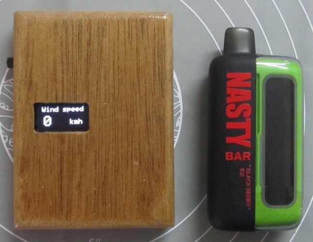
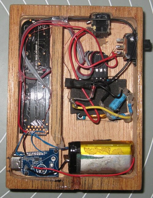
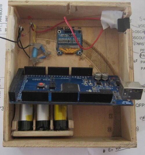
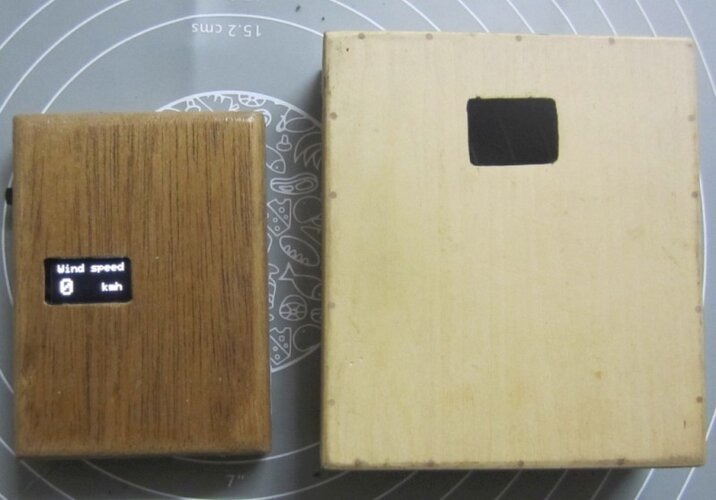
Long story short, I had this idea to convert a Nasty Bar dispo vape into a wind speed meter.
At the moment Im using an Arduino Mega 2560, a 64x32 i2c display and 3 vape batteries, which seems a bit over the top for one input from the spinning cups.
So I pulled a dispo vape apart to see whats inside.
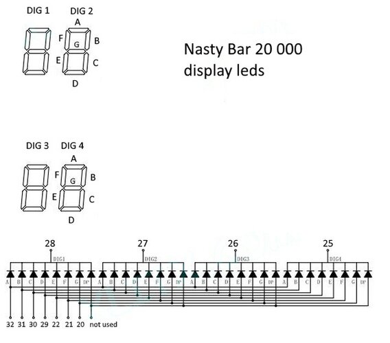
Turns out, if the dispo has a screen its usually a bunch of leds driven by a micro controller (thats where the embedded part comes in).
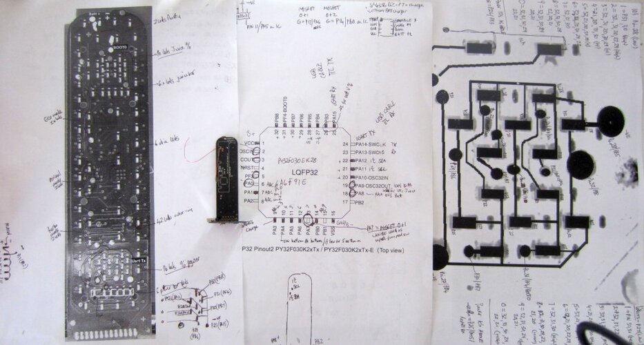
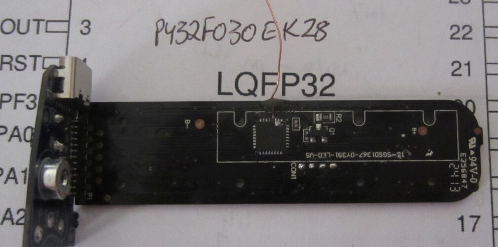
The one in the Nasty bar is a PY32F030EK28. LQFP32, according to the datasheet its 30 I/O pins, 8K ram and 64K flash running at 48Mhz, so twice the performance of an Arduino UNO.
Theres a person on Github that made a PY32Duino board using one of these chips, goes by the username of HALFSWEET, Chinese alas, so very little docs in English.
IOsetting on Github has PY32 templates but Im not a coder so no idea what to do with them.
So far Ive managed to erase the chip using a serial-USART cable and the PuyaISP software, chip had read protect enabled (fancy that, a China vape that doesnt want you to spy on their firmware, lol)
hence the erase.
I tried uploading a blink file in Arduino IDE and one of the leds that is connected to the UART Tx flashed indicating traffic, but nothing happened on reset.
So I was wondering what software I would need to use to develop an app on this IC?
Most of the Puya docs are in Chinese and the ones in English are mainly just data sheets.
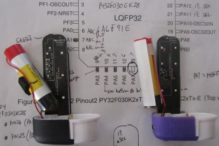
Heres some pics, bottom of the pcb showing the little 7mmx7mm ic with a reset wire soldered onto pin4 because it wasnt broken out to a pad anywhere.
The 4 soldered pads on CON1 are SWD, but the J-Link debugger I bought was a clone and gets blocked by the official Segger drivers.
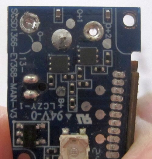
Pic of the bottom power board showing the 2x 6pin power mosfets, NP1216, 12V 16A out of something the size of a rice grain.
I thought it would be nice to have a resources page on the forum with whats inside the thrown away vapes, might help others, but it helps nobody if only Im aware of it.
The Vapengin Mars 2 has an obscure ic that I couldnt find any info on and its a smaller LQFP24 5mmx5mm, MC9904BOZG.
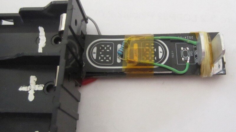
But I turned one into a battery charger as it has a LP4073 ic which is 1amp capable.
I changed the 2.4K resistor which limits charging to 500ma to a 1.8k one, now it charges at 900ma, gets a bit hot hence the need for a heatsink.
U1 is the MC9904, Q! and Q3 are mosfets, 2209 Wm, once again some obscure chip with no datasheets.
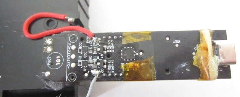
Anyway, it charges a Samsung 3000mah in 1 hour from 3.8v to a max of 4.15v, no more need to buy expensive Nitecores.
At the moment Im using an Arduino Mega 2560, a 64x32 i2c display and 3 vape batteries, which seems a bit over the top for one input from the spinning cups.
So I pulled a dispo vape apart to see whats inside.
Turns out, if the dispo has a screen its usually a bunch of leds driven by a micro controller (thats where the embedded part comes in).
The one in the Nasty bar is a PY32F030EK28. LQFP32, according to the datasheet its 30 I/O pins, 8K ram and 64K flash running at 48Mhz, so twice the performance of an Arduino UNO.
Theres a person on Github that made a PY32Duino board using one of these chips, goes by the username of HALFSWEET, Chinese alas, so very little docs in English.
IOsetting on Github has PY32 templates but Im not a coder so no idea what to do with them.
So far Ive managed to erase the chip using a serial-USART cable and the PuyaISP software, chip had read protect enabled (fancy that, a China vape that doesnt want you to spy on their firmware, lol)
hence the erase.
I tried uploading a blink file in Arduino IDE and one of the leds that is connected to the UART Tx flashed indicating traffic, but nothing happened on reset.
So I was wondering what software I would need to use to develop an app on this IC?
Most of the Puya docs are in Chinese and the ones in English are mainly just data sheets.
Heres some pics, bottom of the pcb showing the little 7mmx7mm ic with a reset wire soldered onto pin4 because it wasnt broken out to a pad anywhere.
The 4 soldered pads on CON1 are SWD, but the J-Link debugger I bought was a clone and gets blocked by the official Segger drivers.

Pic of the bottom power board showing the 2x 6pin power mosfets, NP1216, 12V 16A out of something the size of a rice grain.

I thought it would be nice to have a resources page on the forum with whats inside the thrown away vapes, might help others, but it helps nobody if only Im aware of it.
The Vapengin Mars 2 has an obscure ic that I couldnt find any info on and its a smaller LQFP24 5mmx5mm, MC9904BOZG.
But I turned one into a battery charger as it has a LP4073 ic which is 1amp capable.
I changed the 2.4K resistor which limits charging to 500ma to a 1.8k one, now it charges at 900ma, gets a bit hot hence the need for a heatsink.

U1 is the MC9904, Q! and Q3 are mosfets, 2209 Wm, once again some obscure chip with no datasheets.

Anyway, it charges a Samsung 3000mah in 1 hour from 3.8v to a max of 4.15v, no more need to buy expensive Nitecores.


