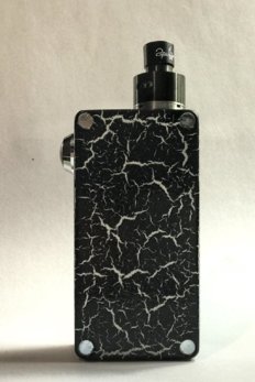
Did you ever watch Dexter?Sorry but looks more like Freddy Kruger theme to me with all the blood.
Navigation
Install the app
How to install the app on iOS
Follow along with the video below to see how to install our site as a web app on your home screen.

Note: this_feature_currently_requires_accessing_site_using_safari
More options
You are using an out of date browser. It may not display this or other websites correctly.
You should upgrade or use an alternative browser.
You should upgrade or use an alternative browser.
DIY Mod build Q&A.
- Thread starter TylerD
- Start date
I thought I just chirp in here to explain N (negative) channel MOSFET, as most of you will use in these builds.
What is a MOSFET?
What is a MOSFET?
- Its a Metal Oxide Semi-conductor Field Effect Transistor (for purposes of this box mod application, a simple switch)
- For heavens sake its not a feckin chip!
- G = Gate (when you apply a + (positive) voltage, the switch is ON
- D = Drain (the terminal that you connect to your coil's - [negative] side)
- S = Source (the terminal that you connect to your battery's - [negative] terminal)
- Current flows from D (Drain) to S (Source) when G (Gate) is more positive than S (Source) // a simple switch when + is connected to G, its ON, and disconnected and/or connected to - (negative) its OFF. [ therefore the 15k resitor connected between G and S].
- A MOSFET has a way longer life span than a mechanical switch
- A MOSFET is minute in size compared to a mechanical switch for the same current (Amp) rating - just look at the size of a 60A direct current mechanical switch, its bigger than the box mod.
- Over time a MOSFET will keep its low on resistance (milli-ohms), as where a mechanical switch's on-resistance will increase over time and lead to arching and increased voltage drops.
- Maybe not important in this application, but its a silent switch compared to high current mechanical switches.
Last edited:
Did you ever watch Dexter?
No! the only Dexter I saw once was a comedy series of a small sweet African American boy.
Thanks for the info @johan ! Nice to know exactly what we working with.I thought I just chirp in here to explain N (negative) channel MOSFET, as most of you will use in these builds.
What is a MOSFET?
What does the terminals on the MOSFET stand for?
- Its a Metal Oxide Semi-conductor Field Effect Transistor (for purposes of this box mod application, a simple switch)
- For heavens sake its not a feckin chip!
How does the MOSFET work?
- G = Gate (when you apply a + (positive) voltage, the switch is ON
- D = Drain (the terminal that you connect to your coil's - [negative] side)
- S = Source (the terminal that you connect to your battery's - [negative] terminal)
Why use a MOSFET instead of a mechanical switch?
- Current flows from D (Drain) to S (Source) when G (Gate) is more positive than S (Source) // a simple switch when + is connected to G, its ON, and disconnected and/or connected to - (negative) its OFF. [ therefore the 15k resitor connected between G and S].
Happy building - hope this assist in understanding what you guys are building.
- A MOSFET has a way longer life span than a mechanical switch
- A MOSFET is minute in size compared to a mechanical switch for the same current (Amp) rating - just look at the size of a 60A direct current mechanical switch, its bigger than the box mod.
- Over time a MOSFET will keep its low on resistance (milli-ohms), as where a mechanical switch's on-resistance will increase over time and lead to arching and increased voltage drops.
- Maybe not important in this application, but its a silent switch compared to high current mechanical switches.
I loved the Dexter series.No! the only Dexter I saw once was a comedy series of a small sweet African American boy.
I loved the Dexter series.
I never saw blood in that series, although I did not see them all?
I thought I just chirp in here to explain N (negative) channel MOSFET, as most of you will use in these builds.
What is a MOSFET?
What does the terminals on the MOSFET stand for?
- Its a Metal Oxide Semi-conductor Field Effect Transistor (for purposes of this box mod application, a simple switch)
- For heavens sake its not a feckin chip!
How does the MOSFET work?
- G = Gate (when you apply a + (positive) voltage, the switch is ON
- D = Drain (the terminal that you connect to your coil's - [negative] side)
- S = Source (the terminal that you connect to your battery's - [negative] terminal)
Why use a MOSFET instead of a mechanical switch?
- Current flows from D (Drain) to S (Source) when G (Gate) is more positive than S (Source) // a simple switch when + is connected to G, its ON, and disconnected and/or connected to - (negative) its OFF. [ therefore the 15k resitor connected between G and S].
Happy building - hope this assist in understanding what you guys are building.
- A MOSFET has a way longer life span than a mechanical switch
- A MOSFET is minute in size compared to a mechanical switch for the same current (Amp) rating - just look at the size of a 60A direct current mechanical switch, its bigger than the box mod.
- Over time a MOSFET will keep its low on resistance (milli-ohms), as where a mechanical switch's on-resistance will increase over time and lead to arching and increased voltage drops.
- Maybe not important in this application, but its a silent switch compared to high current mechanical switches.
Thanks @johan !
That was awesome!
Just a question, how does the mechanical switch in the Reo compare with a Mosfet?
Maybe the Reo should have a mosfet?
I never saw blood in that series, although I did not see them all?
I don't think you saw the same Dexter then because there was blood everywhere, all the time
With him being a blood spatter analyst for the Miami police department, and a serial killer...blood was sort of the theme of the whole show
I don't think you saw the same Dexter then because there was blood everywhere, all the time
With him being a blood spatter analyst for the Miami police department, and a serial killer...blood was sort of the theme of the whole show
That series I totally missed
Thanks @johan !
That was awesome!
Just a question, how does the mechanical switch in the Reo compare with a Mosfet?
Maybe the Reo should have a mosfet?
No not necessary in Reo, as the Reo's switch mechanism is totally different from a commercial mechanical switch.
@johan
Where would on get the solid copper wire locally?
Any electrical- or electronic supply store (you can even get it from workshops that do motor and/or alternator rewindings).
Just a warning solid copper is an absolute pain to work with.@johan
Where would on get the solid copper wire locally?
FYI the kit comes with silicone sheathed stranded tinned copper core cable.
Just a warning solid copper is an absolute pain to work with.
FYI the kit comes with silicone sheathed stranded tinned copper core cable.
That will make it easier for the guys that don't do it everyday, but with the correct type of flux, good soldering iron (>40W) and right tools, it is not that difficult.
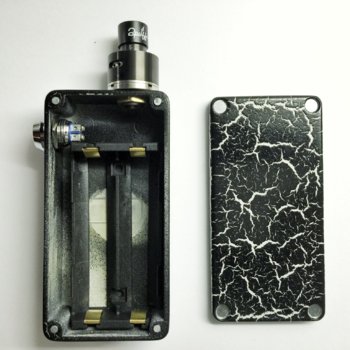
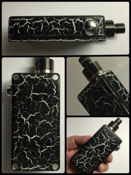
I finished the paint job on mine, fitted the battery sled and installed the switch, 510 and the magnets. I will be doing the wiring and finishing during the week.
In hindsight, I wish I had installed the magnets before I started painting. After taking these pics I did paint the magnets black by hand. Not ideal but it works.
Also I eyeballed the switch and 510 location - templates are for sissies! I did consider mounting the switch on top (next to the 510, like a Reo) but that would have resulted in the edge of the switch touching the edge of the 510, which I thought would look cluttered.
I am very happy with how it came out


Attachments
Awesome!!! Looks damn sexy! Never got to my wiring yesterday. I just need to finish it this week!I finished the paint job on mine, fitted the battery sled and installed the switch, 510 and the magnets. I will be doing the wiring and finishing during the week.
In hindsight, I wish I had installed the magnets before I started painting. After taking these pics I did paint the magnets black by hand. Not ideal but it works.
Also I eyeballed the switch and 510 location - templates are for sissies! I did consider mounting the switch on top (next to the 510, like a Reo) but that would have resulted in the edge of the switch touching the edge of the 510, which I thought would look cluttered.
I am very happy with how it came out
View attachment 28877
View attachment 28875
Nice one... I was looking into doind the same with a mine when I get it... that crackling paint is the #@%.. hehe... I did it the first time a couple of years back with a PC of mine... black underneath and the white crackling over the top... looked pretty damn neat!!!I finished the paint job on mine, fitted the battery sled and installed the switch, 510 and the magnets. I will be doing the wiring and finishing during the week.
In hindsight, I wish I had installed the magnets before I started painting. After taking these pics I did paint the magnets black by hand. Not ideal but it works.
Also I eyeballed the switch and 510 location - templates are for sissies! I did consider mounting the switch on top (next to the 510, like a Reo) but that would have resulted in the edge of the switch touching the edge of the 510, which I thought would look cluttered.
I am very happy with how it came out
View attachment 28877
View attachment 28875
but I have a different idea I want to try out for the mod, will see how it comes out eventually , hehe
Thanks guys - I actually landed up spending another 2 hours on the wiring last night. All that's left is for me to hook up the positive terminal to the 510 and the MOSFET and it should be up and running.
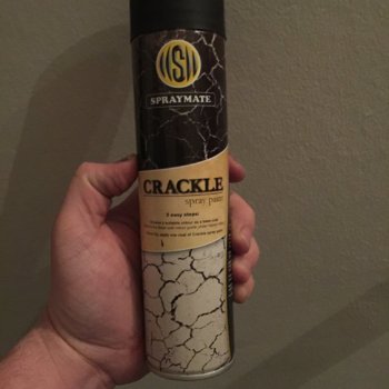
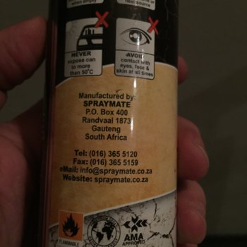
For those of you interested in the paint job, I used a product called Crackle. Basically it's a paint that forms cracks while it is drying, which shows the base coat underneath.
In total there are 4 different products I used:
1. Primer
2. White base coat
3. Crackle black
4. Clear Lacquer
A bit of a nightmare to work with, but thanks to a hot air heater it dried quickly.
I do suggest you warm up the cans of paint before you start spraying. Also with the crackle, the thicker you spray it, the larger the final cracks will be. As you can only spray one coat (otherwise the effect gets ruined) I suggest you spray it thicker rather than thin, but don't spray so much that it starts to run.
I bought all the items at my local Builder's Warehouse. Crackle is made by www.spraymate.co.za


Have u worked out yet how u are doing the soldering on the 510?Thanks guys - I actually landed up spending another 2 hours on the wiring last night. All that's left is for me to hook up the positive terminal to the 510 and the MOSFET and it should be up and running.
For those of you interested in the paint job, I used a product called Crackle. Basically it's a paint that forms cracks while it is drying, which shows the base coat underneath.
In total there are 4 different products I used:
1. Primer
2. White base coat
3. Crackle black
4. Clear Lacquer
A bit of a nightmare to work with, but thanks to a hot air heater it dried quickly.
I do suggest you warm up the cans of paint before you start spraying. Also with the crackle, the thicker you spray it, the larger the final cracks will be. As you can only spray one coat (otherwise the effect gets ruined) I suggest you spray it thicker rather than thin, but don't spray so much that it starts to run.
I bought all the items at my local Builder's Warehouse. Crackle is made by www.spraymate.co.za
View attachment 28893 View attachment 28892
Have u worked out yet how u are doing the soldering on the 510?
There are videos on youtube covering soldering of the 510 but basicall you disassemble the connector and slide the parts on the wire. Then solder the wire into the 510 pin the reassemble
Have u worked out yet how u are doing the soldering on the 510?
I have completely removed the positive pin from the 510. If you further strip it down you can remove the actual pin from the white delrin plastic (there is also a spring, and a TINY Oring to be removed - make sure you don't lose these.). I am planning to solder the positive pin with one wire, then reassemble the positive pin, and then insert it into the 510. The positive pin wire will then be soldered to the left positive post on the battery sled (I have a wire running as a jumper inbetween the first and second positive posts of the sled). I am aiming to use the left post as the center meeting point for all positive wires.
I am a little worried that the MOSFET 'chip' - (just pulling @johan's leg) got too hot while soldering, but hopefully it will survive the process.
Similar threads
- Replies
- 1
- Views
- 117
- Replies
- 2
- Views
- 295
- Replies
- 2
- Views
- 200
- Replies
- 83
- Views
- 6K


