I don't have a clue what you are saying but is this the way we're on now ?Soooooo ... I calculated the length of rod for the transducer at like 7Km or thereabouts, so even a quarter wavelength would have meant almost a kilometer long "probe", so I canned that and did a thumb suck of 75mm and decided to adjust the signal generators frequency as apposed to adjusting the length of "probe", and ... for those that don't know how the "old fashioned method" of finding the resonant frequency of a coil works ... an inductor, (or coil), draws maximum current at resonant frequency, (as the current and voltage waveforms move from 90 degrees out of phase to perfectly in phase).
So by placing one scope probe across a shunt resistor, and another across the transducer, one gets two scope traces, one of voltage, and one of current, and it's a fairly simple? exercise of adjusting the frequency until the current sine wave is at it's highest, which should at that point also be in phase with the voltage sine wave ... which kinda happened ... (give or take about 10 degrees), and I carried on ... with zero happening in the beaker.
I was pushing some 20Watts into the transducer at this point, so ... I continued increasing the voltage, expecting something ... anything? to start happening, (at this point I should add that the amplifier was in bridge mode, meaning a potential 400Watt output with soft clipping ... more commonly known as DC at clipping!).
So somewhere between the initial 20 and some 400Watts? into a device that was only good for some 50 ... things got just a tad warm, and started emulating Red Indian territory ... with a few smoke signals, (thankfully from the cabling), albeit that the transducer was a tad warm ... but that's not where it ends ...
Those that have cooked inductors or transformers know that the external temperature goes up further even after disconnecting the supply, due to the (MUCH HOTTER) core temperature requiring time to radiate outwards, and it's about that time that I picked up the transducer, and surprised my Domestic Executive with my command of, (four letter military), vocabulary ...
{now thats already waaaaaaay too much incriminating information, so I'll now apply what the Americans refer to as the 5th amendment, and in SA, what we call "the Zuma", and shut up!}
Navigation
Install the app
How to install the app on iOS
Follow along with the video below to see how to install our site as a web app on your home screen.

Note: this_feature_currently_requires_accessing_site_using_safari
More options
You are using an out of date browser. It may not display this or other websites correctly.
You should upgrade or use an alternative browser.
You should upgrade or use an alternative browser.
Weekend Projects
- Thread starter Resistance
- Start date
-
- Tags
- weekend
I don't have a clue what you are saying but is this the way we're on now ?
LMAO ... I have the attention span of a flea as you know, so it's "business as usual", same, same, concurrent multiple projects
Would a springloaded centre punch not crack/break it?
I had a tough day I can't think right now.You're wasting your time with a drill, however the center punch may well crack the glue / epoxy, and I'd say it's worth a try, as would the soaking in acetone or other solvents ... btw ...the hammer requires lots of gentle taps as apposed a single blow with a 100 ton hydraulic hammer, the intention being to crack the glue/epoxy bonding
I see if I can think of something over the weekend.
I'm worried about damaging the casing. It is aluminium. I'm going to give it an acetone bath tonight and if that does not work I'll give the drill a bash. I'm not to worried about damaging them as they are chap as nails.
I'm worried about damaging the casing. It is aluminium. I'm going to give it an acetone bath tonight and if that does not work I'll give the drill a bash. I'm not to worried about damaging them as they are chap as nails.
I wouldnt bother with solvents, Im thinking the mechanics of it getting down underneath the magnet are zero. The topmost melted glue layer will act as a barrier.
Id go straight to heat, probably a pencil torch on a corner to get the glue to release. It shouldnt affect the magnet and you should be able to lift it out with a metal ruler/bar.
Well done! ... Those are brilliant ... Do you have a wood lathe?
O ... and next time
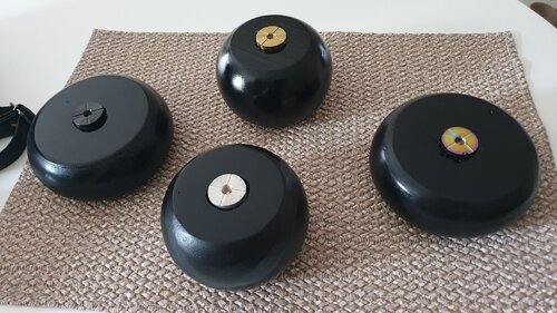
I’m bought the wood buns from a local hardware shop for around R30 each. A little fine sanding, drilling, spraying with black then a clear coat and voila! They costed less than the retail price for one and they look darn awesome on the shelfWell done! ... Those are brilliant ... Do you have a wood lathe?
O ... and next timeyou make more, gimmie a shout, and I'll get a pack of these inserts for wood, retap them for M7*0.5, and swop you for the heatsinked 510 sockets you're using

Lovely.
They look like professional bowling balls. They look awesome!
So once again, I am of "limited pics" ... sowwie  ... Once I get going, I get the job done, and pictures along the way generally only happen if they coincide with a coffee / snack break, (clearly there weren't any with this job).
So ... I have a friend who shall remain nameless for fear of recrimination, that has a Voopoo Drag that also had a pair of stripped 510 mounting screws. There were clearly a few previous attempts at repairs, as I had to dissolve the super glue and some other epoxy? off the inside of the unit, and remove remnants of some kind of self tapping screw? from one of the originally M2 fine holes.
After this had been done, I drilled and retapped the 510 socket to M3 fine, re soldered and reattached everything with new stainless M3 screws, and ... reassembled the unit.
For anyone reassembling one of these devices ... Fold a piece of stiff plastic cut to size, (one of the A4 pieces used in laser printers for PCB positive manufacture will do the trick), folded over the case on the switch side, to enable the switches to slide easily into place without binding
It took about 4 failed attempts before I worked out the folded plastic trick ... and no smart comments about an idiot doing the same thing repeatedly, expecting a different result please
O ... and Yes! ... it needs a bloody good external cleaning / buffing urgently, however I'm leaving that for the owner to tackle
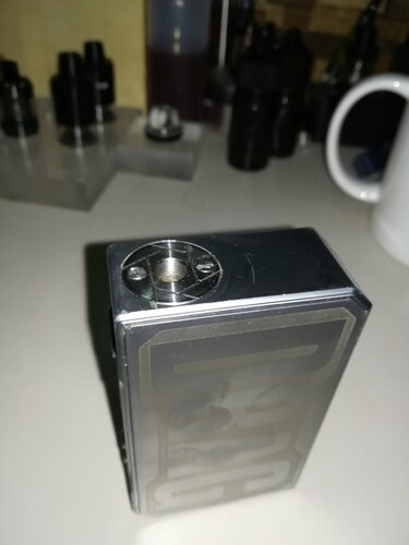
So ... I have a friend who shall remain nameless for fear of recrimination, that has a Voopoo Drag that also had a pair of stripped 510 mounting screws. There were clearly a few previous attempts at repairs, as I had to dissolve the super glue and some other epoxy? off the inside of the unit, and remove remnants of some kind of self tapping screw? from one of the originally M2 fine holes.
After this had been done, I drilled and retapped the 510 socket to M3 fine, re soldered and reattached everything with new stainless M3 screws, and ... reassembled the unit.
For anyone reassembling one of these devices ... Fold a piece of stiff plastic cut to size, (one of the A4 pieces used in laser printers for PCB positive manufacture will do the trick), folded over the case on the switch side, to enable the switches to slide easily into place without binding
It took about 4 failed attempts before I worked out the folded plastic trick
O ... and Yes! ... it needs a bloody good external cleaning / buffing urgently, however I'm leaving that for the owner to tackle

Wow you fixed our friend's mod. Cool!...So once again, I am of "limited pics" ... sowwie... Once I get going, I get the job done, and pictures along the way generally only happen if they coincide with a coffee / snack break, (clearly there weren't any with this job).
So ... I have a friend who shall remain nameless for fear of recrimination, that has a Voopoo Drag that also had a pair of stripped 510 mounting screws. There were clearly a few previous attempts at repairs, as I had to dissolve the super glue and some other epoxy? off the inside of the unit, and remove remnants of some kind of self tapping screw? from one of the originally M2 fine holes.
After this had been done, I drilled and retapped the 510 socket to M3 fine, re soldered and reattached everything with new stainless M3 screws, and ... reassembled the unit.
For anyone reassembling one of these devices ... Fold a piece of stiff plastic cut to size, (one of the A4 pieces used in laser printers for PCB positive manufacture will do the trick), folded over the case on the switch side, to enable the switches to slide easily into place without binding
It took about 4 failed attempts before I worked out the folded plastic trick... and no smart comments about an idiot doing the same thing repeatedly, expecting a different result please
O ... and Yes! ... it needs a bloody good external cleaning / buffing urgently, however I'm leaving that for the owner to tackle
View attachment 222927
The pic qualifies you for another beer with our friend. I'll drink tea to that!
Hey heeeeey ... I think I know what that is
I'm looking forward to seeing that lil' beastie perform
With your help of course. You are indeed the creator of a certain thingymabob I am interested in.Hey heeeeey ... I think I know what that is
I'm looking forward to seeing that lil' beastie perform
With the greatest of pleasure budWith your help of course. You are indeed the creator of a certain thingymabob I am interested in.
Petrolheads refer to vehicles with seriously improved mechanicals as "Sleepers", we're going to have to invent a term for doing the same with old school mods and tanks
I got a lot.of words ,but it's just words. We need to vote on this.With the greatest of pleasure bud
Petrolheads refer to vehicles with seriously improved mechanicals as "Sleepers", we're going to have to invent a term for doing the same with old school mods and tanks
A term we also use for cars that's already used. We jus say "ge-mod".
https://thesaurus.yourdictionary.com/modification
How about touched. For touched up. Touch by a a skillset?I got a lot.of words ,but it's just words. We need to vote on this.
A term we also use for cars that's already used. We jus say "ge-mod".
https://thesaurus.yourdictionary.com/modification
Hey @Intuthu Kagesi did you touch that mod?
How about touched. For touched up. Touch by a a skillset?
Hey @Intuthu Kagesi did you touch that mod?
Maybe Sleeper is a good name, as thinking back to that Tesla I did ... It's such a diminutive looking mod, but man that thing kicks like a mule now, it's certainly a wolf in sheeps clothing
I'll sleep on it
Maybe Sleeper is a good name, as thinking back to that Tesla I did ... It's such a diminutive looking mod, but man that thing kicks like a mule now, it's certainly a wolf in sheeps clothing
Ja we stick to car terminology while I take a puff on my RatMod!
Ja we stick to car terminology while I take a puff on my RatMod!
I really like that!
Outside of the Petrolhead definition of a Rat rod, (a mechanically customised car with a deliberately worn-down, or unfinished outward appearance), with respect to the Chinese Calendar ... I'm a Metal Rat
On some perverse level, it's pretty kewl ... The American way - Brute force and ignorance
I need that Corona helmet!
Ive been busy this last week building a KAP rig (kite aerial photography).
Long story short, new fridge arrived and I saved the plastic thinking it would make a decent box kite.
So, box kite built, checking it out and pondering, I stuck a keychain spy cam on it... and down the rabbit hole I went.
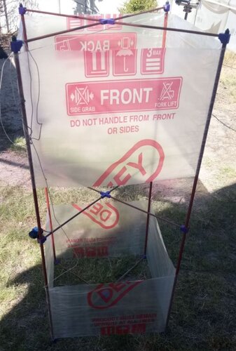
While "netting" I checked out ways to put a camera on the kite, turned out a picavet suspension rig is the way to go, back to the garage to bend some 3mm alu strip. The picavet cross I found on thingiverse so that got printed in solid ABS.
Then I remembered how hard a bamboo and black bag kite pulled that I made back in the mid '80's, so next a proper kite reel got put together.
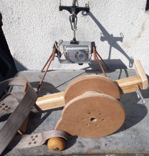
Its called a strato spool, very nice with body strap, reel lock and a brake, I had a piece of 16mm thick mdf which defs looked like a strato spool to me.
Tadaa. The camera is a Canon powershot A480 from 2009 and it runs a CHDK script to take pics every 30 seconds till the batteries run flat, an hour give or take.
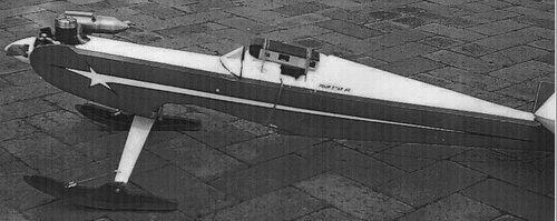
Im no stranger to aerial photos, back in the day (July 2000) I rubber banded a kodak instamatic 110 to a rc plane, the 4Star40. pics for the record.
The field I flew at was water logged in winter so I made a pair of water ski's out of countertop formica.
Aerial view of the field, Nelson's Creek on the outskirts of Paarl.
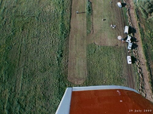
Needless to say I didnt finish the full 26 exp roll, it was very tedious because I had to kill the engine at altitude to stop motion blur, land the plane dead stick, advance the film slide, start and take off again.
With KAP its a whole other game, 120 shots in an hour @ 30 secs per shot and I dont need to print them all out to see which are keepers.
Long story short, new fridge arrived and I saved the plastic thinking it would make a decent box kite.
So, box kite built, checking it out and pondering, I stuck a keychain spy cam on it... and down the rabbit hole I went.

While "netting" I checked out ways to put a camera on the kite, turned out a picavet suspension rig is the way to go, back to the garage to bend some 3mm alu strip. The picavet cross I found on thingiverse so that got printed in solid ABS.
Then I remembered how hard a bamboo and black bag kite pulled that I made back in the mid '80's, so next a proper kite reel got put together.
Its called a strato spool, very nice with body strap, reel lock and a brake, I had a piece of 16mm thick mdf which defs looked like a strato spool to me.
Tadaa. The camera is a Canon powershot A480 from 2009 and it runs a CHDK script to take pics every 30 seconds till the batteries run flat, an hour give or take.

Im no stranger to aerial photos, back in the day (July 2000) I rubber banded a kodak instamatic 110 to a rc plane, the 4Star40. pics for the record.
The field I flew at was water logged in winter so I made a pair of water ski's out of countertop formica.

Aerial view of the field, Nelson's Creek on the outskirts of Paarl.

Needless to say I didnt finish the full 26 exp roll, it was very tedious because I had to kill the engine at altitude to stop motion blur, land the plane dead stick, advance the film slide, start and take off again.
With KAP its a whole other game, 120 shots in an hour @ 30 secs per shot and I dont need to print them all out to see which are keepers.
Last edited:
Similar threads
- Replies
- 0
- Views
- 188
- Replies
- 6
- Views
- 1K
- Replies
- 1
- Views
- 93


