Navigation
Install the app
How to install the app on iOS
Follow along with the video below to see how to install our site as a web app on your home screen.

Note: this_feature_currently_requires_accessing_site_using_safari
More options
You are using an out of date browser. It may not display this or other websites correctly.
You should upgrade or use an alternative browser.
You should upgrade or use an alternative browser.
Pwm
- Thread starter Resistance
- Start date
-
- Tags
- pwm
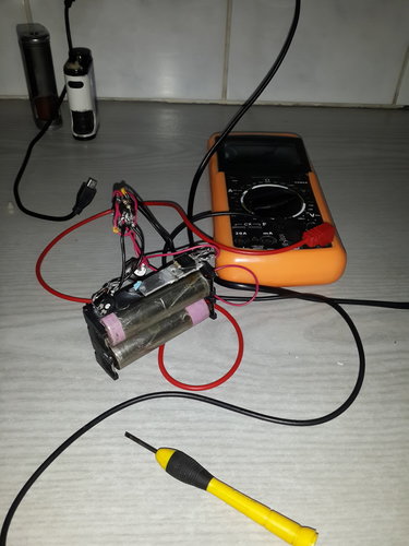
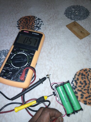
A failed attempt at a pwm mod.
The batts are my test batts. I only use it for stuff like this. I dont use it for vaping.
The schematic I got might be the problem, but will sort it out once I get another schematic
what went wrong?
which schematic did you use?
Found one on the net, I think its from modmaker.
im not giving up just need to look for something else or if someone has one thats willing to share with me it would be great.
im not giving up just need to look for something else or if someone has one thats willing to share with me it would be great.
what went wrong?
which schematic did you use?
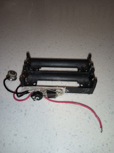
Ok, so after fiddling with this failed experiment I decided to look at more, or should I say other options to get this to work.
I took out the 555 timer and fitted the pot directly to the MOSFET.
I took out the 555 timer and fitted the pot directly to the MOSFET.
Now I need to build a case.
what went wrong?
which schematic did you use?
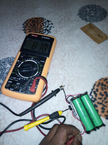
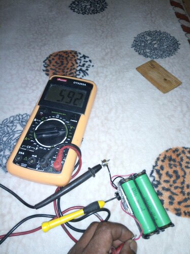
I have made some progress.
Hi Resistance,
I was searching through the forum and came across your post ... Don't know if you've made any progress? but can suggest the circuit I'm using if you haven't;
My circuit uses the LMC555, which is a CMOS version of the 555, and will work with a 1.5V supply, (2.7 in this cct), and an IRLB3034 mosfet, (rated at 195 Amps), meaning you could use this, (as I do), with a single 18650, (although not in the attached cct), I would highly recommend the addition of a fast acting PTC of around 2E rated at 25-30A, (Mantech have a huge selection).
Edited ->Rev.2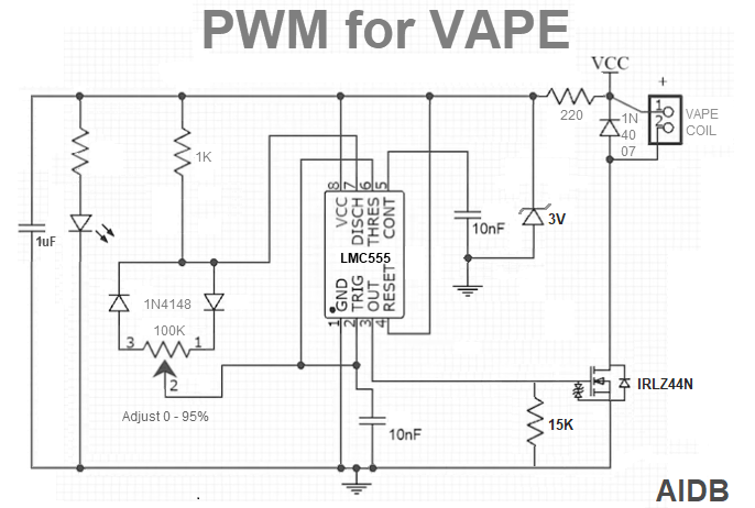

Attachments
Last edited:
Hi Resistance,
I was searching through the forum and came across your post ... Don't know if you've made any progress? but can suggest the circuit I'm using if you haven't;
My circuit uses the LMC555, which is a CMOS version of the 555, and will work with a 1.5V supply, (2.7 in this cct), and an IRLB3034 mosfet, (rated at 195 Amps), meaning you could use this, (as I do), with a single 18650, (although not in the attached cct), I would highly recommend the addition of a fast acting PTC of around 2E rated at 25-30A, (Mantech have a huge selection).
View attachment 205766
I'll add to "electric smoke's" sound advice, def add an on/off switch.
I've had 2 mosfets fail into a full short during idle, ie not firing using the fire button.
The main reason was the 555 was always on. I landed up dumping a pair of well roasted 25R's onto the road.
Until Im happy with redesign number 3, this type of mod requires careful supervision at home only.
Hi Blujeenz,
Sound advice! ... We must remember that the 18650's we use are UNPROTECTED, and potentially a bomb of sorts when shorted due to their ultra low internal resistance and chemical makeup
I'm using the original Augvape squonk switch to supply/cut power to EVERYTHING, (ie. in series with VCC in the cct), and ... to keep the unit responsive, include a small decoupling cap, (the 1uF to the far left) to keep the 555 "idling" between puffs. I also have three ptc thermistors in series with VCC, on the battery holder.
I still need to devise some sort of SAFE "standby feature" other than removing the battery(ies) if you have any ideas?
Nope, no other ideas, you seem to have it covered, on/off switch and resettable fuses.
Alas my diy builds dont have the space even for a small 10amp fuse.
Im busy with a redesign of my Pulse 80W due to the safety issues with the naked PWM mod's.
Nope, no other ideas, you seem to have it covered, on/off switch and resettable fuses.
Alas my diy builds dont have the space even for a small 10amp fuse.
Im busy with a redesign of my Pulse 80W due to the safety issues with the naked PWM mod's.
Glad to hear you're looking at a safety redesign
Yes the resettable ones. I was looking at those.Glad to hear you're looking at a safety redesign... Put in a smallish PTC ... jus' make space an' force it in somewhere/anywhere ... or ... worst case scenario; Mantech have "solder in" fuses that are roughly the size of a 1/4W resistor, that go up to 20A

Hi. No I haven't done anything yet. I still have it in my failed experiments box for rework. I have been extremely busy lately,bit I'll have a look at it again when I can. Thanks for the effort,much appreciated.Hi Resistance,
I was searching through the forum and came across your post ... Don't know if you've made any progress? but can suggest the circuit I'm using if you haven't;
My circuit uses the LMC555, which is a CMOS version of the 555, and will work with a 1.5V supply, (2.7 in this cct), and an IRLB3034 mosfet, (rated at 195 Amps), meaning you could use this, (as I do), with a single 18650, (although not in the attached cct), I would highly recommend the addition of a fast acting PTC of around 2E rated at 25-30A, (Mantech have a huge selection).
View attachment 205766
Hi Resistance,
I was searching through the forum and came across your post ... Don't know if you've made any progress? but can suggest the circuit I'm using if you haven't;
My circuit uses the LMC555, which is a CMOS version of the 555, and will work with a 1.5V supply, (2.7 in this cct), and an IRLB3034 mosfet, (rated at 195 Amps), meaning you could use this, (as I do), with a single 18650, (although not in the attached cct), I would highly recommend the addition of a fast acting PTC of around 2E rated at 25-30A, (Mantech have a huge selection).
View attachment 205766
I had a 555 timer on the circuit bit it didn't work well so I just used the IRLB3034 with a 15kohm resistor connect through the pot.. wires heated up (not the most ideal wires used) so I put it on hold.
Hi Blujeenz,
I still need to devise some sort of SAFE "standby feature" other than removing the battery(ies) if you have any ideas?
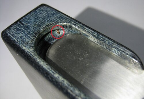
Dont know if it would qualify for your use case, but I drilled a hole through the body from the electronics cavity to the closest batt tube and fed a copper wire through.
So now when I fully close the batt door, it feeds +4.2V to the stripboard, the neg is taken off the source pin of the mosfet and Im using a cmos 7555 with on min of 3v.
I red circled the wire in the pic.
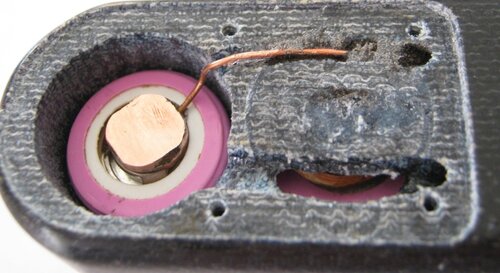
My first attempt was taking the pos off the dual batt stack sending 8.4V to the NE555, but I suspect that pos disk was making kuk under the 510.
I had a 555 timer on the circuit bit it didn't work well so I just used the IRLB3034 with a 15kohm resistor connect through the pot.. wires heated up (not the most ideal wires used) so I put it on hold.
I see from your pics that your wiring was a lil' on the erm "skinny" side
As to using a pot to control a mosfet directly ... NOT a good idea for a number of reasons! ... Primarily because in that mode of operation, you would be using it as a current limiting device, (making your circuit an effective voltage divider), and the mosfet would then have to deal with / dissipate a sh# load of power.
In a PWM configuration however, the power dissipation by the mosfet is minimal, (even at maximum current flow), as the voltage drop across it is typically less than 0.1Volt, with it being turned on fully. The output voltage is based on the duty cycle of the square wave output, ie. a duty cycle of 50:50 = 50% output of whatever the input voltage is.
Dont know if it would qualify for your use case, but I drilled a hole through the body from the electronics cavity to the closest batt tube and fed a copper wire through.
So now when I fully close the batt door, it feeds +4.2V to the stripboard, the neg is taken off the source pin of the mosfet and Im using a cmos 7555 with on min of 3v.
I red circled the wire in the pic.
View attachment 205806
My first attempt was taking the pos off the dual batt stack sending 8.4V to the NE555, but I suspect that pos disk was making kuk under the 510.
View attachment 205807
That's bloody clever
Agreed. I only tested it on the multimeter and once with an RDA connected to see if it would work that way. Then it went on hold.I see from your pics that your wiring was a lil' on the erm "skinny" side
As to using a pot to control a mosfet directly ... NOT a good idea for a number of reasons! ... Primarily because in that mode of operation, you would be using it as a current limiting device, (making your circuit an effective voltage divider), and the mosfet would then have to deal with / dissipate a sh# load of power.
In a PWM configuration however, the power dissipation by the mosfet is minimal, (even at maximum current flow), as the voltage drop across it is typically less than 0.1Volt, with it being turned on fully. The output voltage is based on the duty cycle of the square wave output, ie. a duty cycle of 50:50 = 50% output of whatever the input voltage is.
Similar threads
- Replies
- 2
- Views
- 4K
- Replies
- 3
- Views
- 411
- Replies
- 0
- Views
- 380
- Replies
- 0
- Views
- 254


